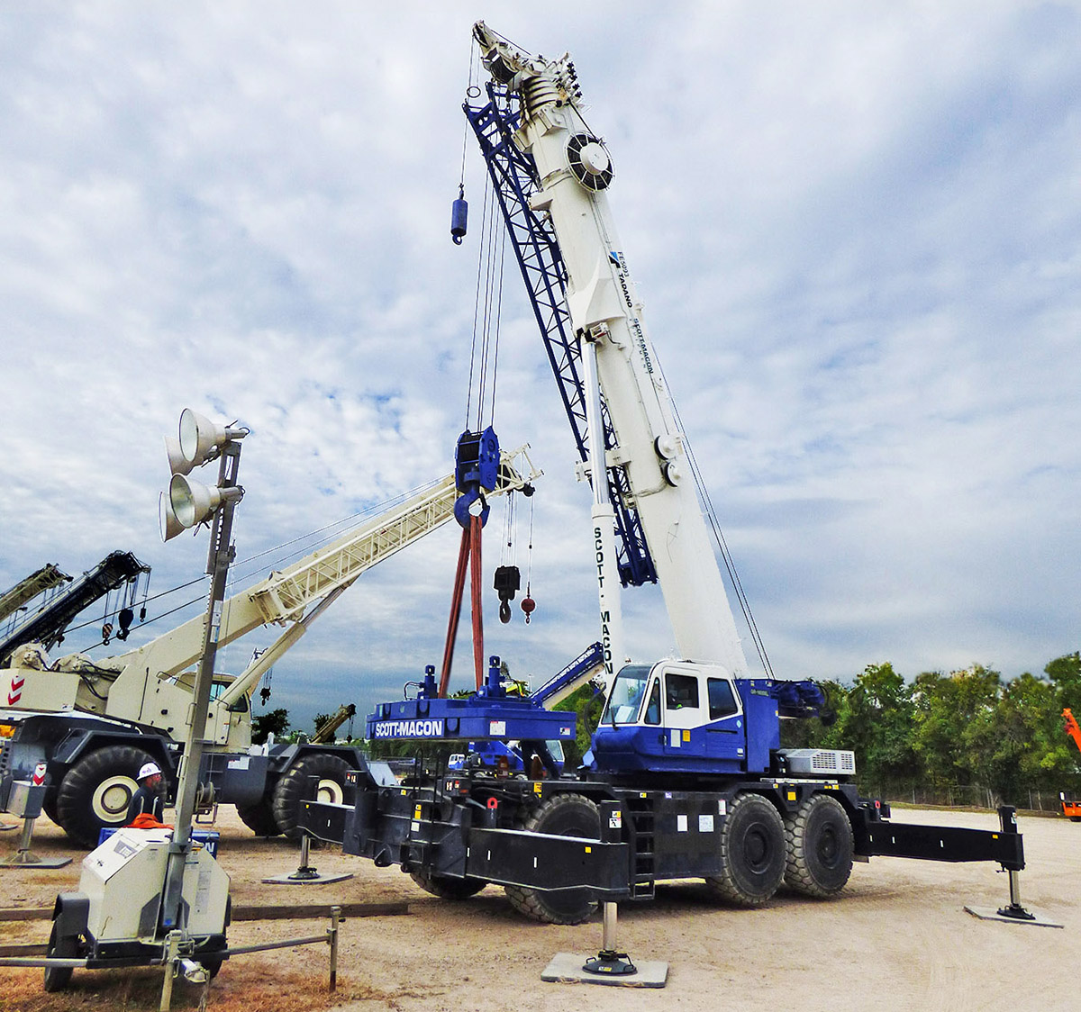
Crane accidents often happen when the crane is improperly set up at the jobsite. Common mistakes that occur are failing to properly use the outriggers or failing to provide large enough cribbing under them to support the crane. It is important to understand the loads being exerted on crane outriggers, the types of supporting surfaces that exist, and how to correctly size outrigger cribbing to support the crane. Determining the amount of weight that is exerted on the outriggers is important to help you make sure the crane has enough support and will not tip over.
Outrigger Load
The amount of weight that a crane’s outriggers will need to safely handle can be determined mathematically. To get the true value, the actual load weight (including rigging) to be lifted must be added to the weight of the crane. This is the “Total Load” that will be exerted on the outriggers during the lift. The math equations that provide an answer are covered later in this article.
The design of the crane’s outrigger pads also come into play. The size and shape make a difference. Circular outrigger pads must be factored differently than square outrigger pads. Also, cranes with smaller pads will more likely need additional outrigger support.
When figuring the weight the outriggers must handle, consider only one outrigger pad to be used for this determination. Why just one pad? That is because you want to safely plan for up to 100% of the Total Load of the pick to potentially be exerted on any one outrigger pad at some point during lifting and maneuvering. For example, when the boom supporting the load is positioned directly over an outrigger.
Soil Considerations
It must now be determined if the ground/soil will support the amount of weight using the outriggers alone, or if additional cribbing (outrigger pad support) will be required. Outriggers can sink into soft soil, allowing the tires to contact the ground and even possibly causing the crane to tip. Proper cribbing reduces a crane’s ground pressure and will keep the crane's tires free of the support surface and the crane level.
You need to determine the type of ground the crane is set on. One way to gain valuable insight into the ability of soil to support loads is by referring to the OSHA 1926, Subpart P Appendix A (see excerpt below). Soil can be classified into three types by compressive strength:
- Type A soils consist of clay, silty clay, sandy clay, and clay loam along with cemented soils such as caliche and hardpan. Soil cannot be Type A if it is fissured; is subject to vibration; has been previously disturbed; or is part of a sloped, layered system. They have a compressive strength of 1.5 tons per square foot (tsf) or greater.
- Type B soils consist of angular gravel (crushed rock), silt, silt loam, and sandy loam along with silty clay loam and sandy clay loam in some cases. Type B soils can also be Type A type soils that are fissured, subject to vibration, or unstable dry rock, along with material that is part of a sloped, layered system. They have a compressive strength greater than 0.5 tons per square foot (tsf), but less than 1.5 tons per square foot (tsf).
- Type C soils consist of gravel, sand, and loamy sand along with submerged soil or submerged rock that is unstable. Type C soils are also material that is part of a sloped, layered system. They have a compressive strength of 0.5 tons per square foot (tsf) or less.
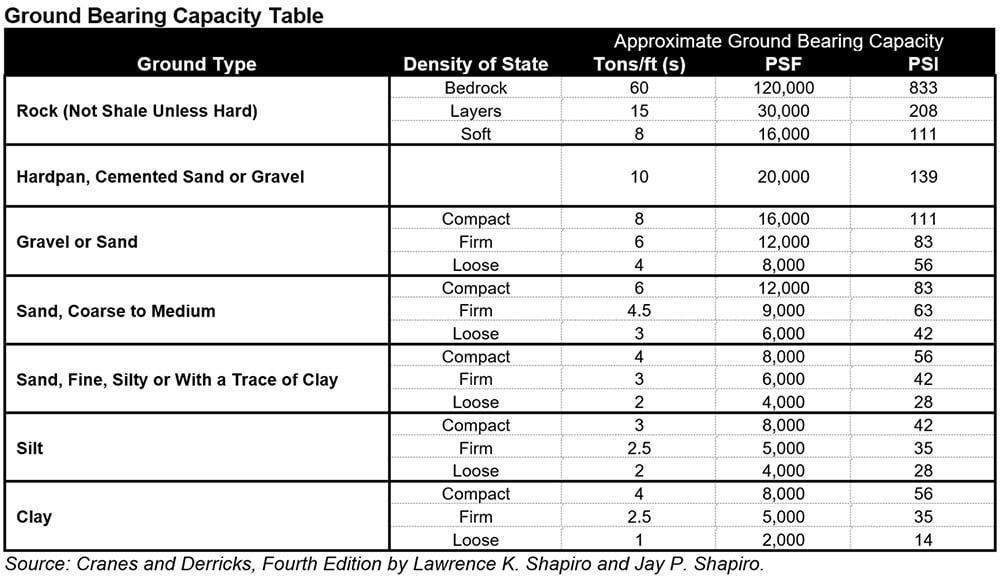
“Many construction sites have Type B or Type C soil, so make sure you are basing calculations on the proper soil type.” The table below is an additional source of information that covers a variety of surfaces. The ultimate ground bearing capacity is already expressed in pounds per square inch.

Doing the Math
Here is an example to help illustrate the concept. “Let’s use a 50-ton crane that weighs 86,000 pounds as our example. Adding the weight of the crane to the crane’s maximum capacity of 100,000 pounds results in 186,000 pounds, what we will refer to as the ‘Total Load.’”
A mathematical equation can be used to determine the bottom surface area of the crane’s outrigger pads. The equation used for a round pad is that which is used for the area of a circle: Pi x radius squared (Pi being 3.14 and the radius being half the diameter of the pad). The surface area equation for a square pad is just: side x side. The crane in this example has round outrigger pads which measure 24 inches in diameter (12 inches in radius). Using the area of a circle equation, the bottom surface area will be approximately 452 square inches.
The Total Load of 186,000 pounds, is then divided by the square inches of just one outrigger pad’s bottom surface area of 452 square inches. This gives you the force in pounds that will be exerted on each square inch of its bottom surface which will equal approximately 411 pounds per square inch.
“[This] example uses Type A soil, and we selected the 1.5 tsf compressive strength as the basis of our example.
“First, the Soil Resistance needs to be converted from tons to pounds. The 1.5 tons per square foot multiplied by 2,000 lbs./ton equals 3,000 pounds per square foot (psf) compressive strength. This is how much pressure in pounds per square foot the soil can support.
“Second, divide the [3,000] pounds per square foot the soil can support by the square inches in one square foot.” The square inches in one square foot is 144 square inches. This will give you the [support] pressure in pounds per square inch (psi). “This provides a comparison of the psi exerted by the crane and the psi of the soil resistance. The crane in this example will exert 411 psi and the soil resistance can support a maximum of 20.83 psi. Therefore, the outrigger’s support area must increase to spread the exerted psi over a larger area.”
In order to find the proper size cribbing required, divide the Total Load of 186,000 pounds on the outrigger pad by the soil resistance of 20.83 pounds per square inch. The cribbing therefore needs to have a contact surface area with the soil of 8,929 square inches.
Now, take the square root of the 8,929 square inches of contact surface area to obtain the dimensions of the square shaped cribbing support to be required. The cribbing dimensions for the outriggers required for this example are 94 inches by 94 inches, or 7 feet 10 inches by 7 feet 10 inches.
Here are the Equations:
- Crane wt. of 86,000 lbs. + Max. Cap. of 100,000 lbs. =
186,000 lbs. Total Load on outriggers
- Bottom surface area of one 24” diameter outrigger pad = Pi x 12” x 12” = 3.14 x 12” x 12” =
452.16 sq. inches (Approx. 452 sq. inches)
- Total Load 186,000 lbs. ÷ 452 sq. inches of one outrigger pad surface =
Approx. 411 lbs. per sq. inch (psi) exerted only on one outrigger pad surface
- 1.5 tons per sq. ft. Soil Compressive Strength x 2,000 lbs. per ton =
3,000 lbs. per sq. ft. Soil Compressive Strength
- 3,000 lbs. per sq. ft. Soil Compressive Strength ÷ 144 sq. inches per sq. ft. =
20.83 lbs. per sq. inch (psi) Soil Compressive Strength
- 186,000 lbs. Total Load ÷ 20.83 psi Soil Compressive Strength =
8,929 sq. inches of support surface needed
- Square root of 8,929 sq. inches of support surface =
94 inches (length of one side of square cribbing)
Additional Points of Consideration
- Avoid point loading, which is a result of reduced surface contact area. Outrigger foundations must be built-up to fully transfer the load to the entire supporting surface area.
- Be sure that the outrigger support cribbing is strong enough to prevent crushing, is free of defects, and is of sufficient length and width.
- “Never block under the outrigger beams, as this changes the crane’s tipping fulcrum.”
- Be sure to check the crane level frequently to make sure the supporting surface is adequately supporting the crane.
- As always, crane operators need to be competent and trained with the cranes and LMI systems being used.
Conclusion
The importance of proper setup and outrigger use by an experienced operator cannot be understated. A stable crane is less likely to tip or drop the load. A high percentage of crane accidents are due to the operator making a swing or pick while the outriggers are retracted. Also, the amount of weight that a crane’s outriggers can safely handle must be determined and if the ground will support the weight using the outriggers alone. Often, extra outrigger pads must be used in conjunction with the crane’s outriggers to safely handle heavy loads on soft or unstable ground.
Scott-Macon Equipment provides DICA outrigger pads that are available for sale from our Parts Department. Our parts personnel are available to assist you by phone at 713-766-4752 or email at parts@smequipment.com as well as in person. For outrigger pad rentals, please contact your sales representative or your local Scott-Macon Equipment branch.
References:
Mobile Crane Outrigger Support. (2014, 1-28). Crane Tech - Tech Tips.
Crane Tech Outrigger Support Article
Shapiro, Lawrence, and Jay Shapiro. Cranes and Derricks, Fourth Edition, McGraw Hill, 2010.
For more information on DICA outrigger pads, click here: DICA Outrigger Pads
For additional articles, click here: Blog | Scott-Macon Equipment (smequipment.com)

-1.jpg)


Comment